Wireless Myoelectric Implant Records High-Quality EMG Signals
Charla L. Howard, PhD; Isaac Myers, PhD; Brian Crofts, MS;
Scott Hiatt, MS; and Daniel McDonnall, PhD
Over the last decade, prosthesis manufacturers have released substantially more dexterous myoelectric prosthetic arms. In spite of the improvements of these advanced myoelectric systems, complete functional adoption of these devices is unacceptably low. Myoelectric devices are rejected by between 23 and 39 percent of users, which is comparable to the rejection of body-powered prostheses (between 26 and 50 percent).1 Amputees cite awkward use and lack of utility of their myoelectric prostheses, as well as dissatisfaction with the ability to perform activities of daily living, as the primary reasons for rejection.2,3 Thus, despite the potential for improved function with a myoelectric device, poor control of the system limits the adoption of advanced arm prostheses.
These issues highlight that the technology for prosthesis control is not at a suitable level to take advantage of advanced prosthetic upper limbs. A large challenge with the implementation of current myoelectric devices is the common use of only two surface electromyography (EMG) electrodes for collection of control signals. Not only limited by the small number of control signals, surface EMG signals have multiple issues that limit their utility for myoelectric control. Intuitive control of precise motion is limited with surface EMG as it is difficult to record isolated signal from a single muscle due to the cross-talk (multiple muscles captured in one signal) that occurs as signals travel through the tissue and skin.4 Further, the quality of the surface recording can be impacted by muscle and skin motion, along with a changing socket environment. Limitations in the control signals extracted from surface EMG signals limit successful implementation of advanced control algorithms and intuitive movement. Thus, these advanced prostheses still require serial selection and control of individual joints and grips, resulting in slow, unnatural motions.
To address these issues, we have developed a myoelectric implant that records 32 channels of intramuscular EMG from multiple residual muscles and transmits these data to an external transceiver placed in the prosthetic socket (see Figure 1). Our objective is to provide simultaneous multidegree-of-freedom prosthesis control, ultimately providing intuitive and dexterous control. This approach supports a high number of independent control signals and provides access to EMG from deep muscles that cannot be accessed with surface electrodes.
The system comprises a hermetic implanted module with eight EMG leads and one reference lead. Each lead contains four single reference electrode sites for 32 total recording channels. The system design allows for independent placement of each lead, enabling access to multiple muscle sites at locations and depths inaccessible by other systems. The implant receives power inductively from an external transceiver and sends digitized EMG data to the transceiver via infrared light.
The safety and function of the implanted system was tested in a six-month animal study to confirm the device can successfully transmit high-quality, low-noise EMG signals that can be used to control a prosthetic device in real time.
Methods
Surgical Procedure
Five canines were implanted with the myoelectric implant in their upper left forelimb for six months to evaluate the safety and function of the implanted system. The study was conducted at a U.S. Department of Agriculture accredited contract research organization under approval by the Institutional Animal Care and Use Committee.
The eight electrode leads extending from the electronics package, each containing four electrodes, were inserted into the long head of the triceps (two), the lateral head of the triceps (three), and one each in the posterior, middle, and anterior portions of the deltoid. A reference electrode lead was placed between the triceps and deltoideous muscles. The leads were placed using a custom insertion tool and secured using a polyethylene anchor built into the end of each lead. The leads also were secured to the fascia to prevent movement.
Data Collection
At the end of the six-month period, the chronic viability of the device functionality was tested by collecting EMG data from each animal while at rest and walking. The EMG signals were sampled at 2,000 Hz. Tests were video recorded to support the analysis.
The external transceiver was held over the implanted device with an adhesive wrap, and the animals also wore a custom vest that was used to carry the processor for data collection. When used with a prosthesis, the transceiver will be mounted in the socket and will transmit the EMG information to the prosthesis, as illustrated in Figure 1, creating an integrated system with no belt-worn components for the user to don.
EMG Data Processing
The transmitted EMG signals were processed to evaluate the signal-to-noise ratio (SNR) for each device during walking. SNR quantifies the difference between the actual signal of interest and the background noise of the channel. A high SNR represents a dynamic range of muscle activation used for myoelectric control improving the accuracy and intuitive feel of the prosthetic control. Low relative noise (high SNR) also allows for rapid detection of the onset of the contraction enabling real-time prosthesis control, increasing the embodiment of the device.
The raw signal was bandpass filtered with cut-off frequencies of 5 and 750 Hz, and the DC offset was removed. The EMG signal recorded at rest was used to characterize the noise of each channel. The root mean square (RMS) of the signal was calculated for each 25-ms (50-sample) window along the length of the signal. For each channel, the individual RMS calculations were binned at 6-µV increments. During the period of quiescent muscle activity, the lowest three occupied bins contained approximately 80 percent of the signal across animals and channels. This portion of the signal was labeled as noise. The signals from the walking trials were windowed and binned in the same manner, and the mean RMS value of the signal contained in the lowest three occupied bins was used as the noise value in the SNR calculation. Muscle activation events during the walking trials were identified using a double threshold (time and amplitude) detection method.5 The start of a muscle activation event was identified when the signal was greater than 2.0 times the noise of that channel for 100 ms. The time threshold was selected as it falls within the time delay range that would be considered to provide real-time control of a prosthesis.6-8 The amplitude threshold was selected to have a low chance of false positives while still identifying the onset of muscle activation. The threshold selections were confirmed by comparing the number of identified events to the number of steps counted in the video recordings of the walking trials.
For each muscle activation event identified, the average RMS over the activation period was calculated. The event SNR (event RMS/channel noise RMS) was calculated and averaged for each channel. The average value includes the early low amplitude (near threshold) period of muscle activation lowering the overall SNR. Thus, to illustrate the full dynamic range of the signal, the SNR also was calculated using the peak RMS of each event. Lower SNR values also could be the result of a channel being located in a less active muscle, resulting in smaller amplitude events. To confirm lower SNR values were the result of less activity and not high noise levels, the average channel SNR was correlated with the channel noise for each device. A large negative correlation would signify that low SNR values were the result of higher noise on the channel. Low or positive correlations would confirm lower SNRs were due to less muscle activation.
Results
Figure 2 shows the 32-channel EMG signal for one animal during walking. Figure 3 shows an example of a quiescent period followed by a muscle activation event measured in the long head of the triceps. These periods were confirmed to correspond to shoulder extension (quiet) and flexion (active) in the video recording.
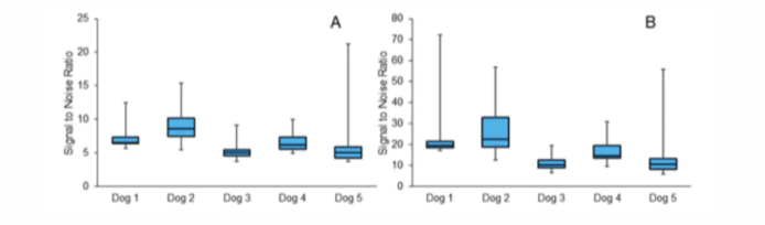
We found that each device had a high, dynamic SNR across all channels. When calculated with low-amplitude, early onset period, the average device SNR was between 5 and 9. Figure 4A illustrates the range of average SNR values across the 32 channels in each device measured with the real-time onset window. However, when the SNR was calculated from the peak of each event, the SNR was much larger (Figure 4B), illustrating the dynamic range of the signal.
The correlation between the SNR and noise for each device was very low and mostly positive (-0.007 – 0.22), confirming that channels with lower SNR values were not due to higher noise levels.
Discussion
The results demonstrate that Ripple’s implanted myoelectric device can transmit high-quality EMG signal after six months of implantation. We found high SNR across all channels, with many devices recording events with a peak SNR greater than 20. There was low noise on all channels, and the lack of correlation between noise and SNR suggests that instances of lower SNR were likely due to lower amplitude muscle activations rather than reduced signal quality. The dynamic SNR was achieved with a very short time threshold for event detection (100 ms), suggesting this system will be able to provide the perception of real-time control for the user. Along with the signal quality, the high-channel count and independence of lead placement offers many benefits over existing myoelectric control systems.
These findings support the use of this device for real-time, simultaneous multiple-degree-of-freedom control of a prosthetic arm. The overall low noise and high relative amplitude of the signal (high SNR) measured with the implanted device will allow signal decode algorithms to rapidly detect the start of muscle activation events and convey this information to the prosthetic limb. Our detection threshold of 100 ms was well below the suggested detection threshold of less than 250 ms.6-8 Additional analysis of shorter time thresholds with higher amplitude thresholds produced similar results in this study. Thus, advanced decode algorithms will likely be able to reduce the muscle activation detection time even further.
The high-quality EMG signal was due to the implantation of the sensors, which eliminated many of the physiological factors that reduce the quality and utility of surface EMG recording. A substantial factor in surface EMG signal amplitude and cross-talk is the thickness of the subcutaneous fat layer the signal must travel through to reach the recording device.4 A model of EMG signal quality found that a 6-mm difference (change from 9 mm to 3 mm) in subcutaneous fat resulted in a 241 percent increase in signal amplitude and a 68 percent decrease in cross-talk.4 These findings suggest that the ability to successfully use a myoelectric device with surface EMG may be limited by the morphology of the amputated limb and that reports of successful prosthesis control using surface EMG may not be applicable to the entire population. However, with device implantation and independent lead placement, the impacts of physiological limb features on signal quality are removed and offer a promise of quality EMG signal for most limb types.
Conclusion
These efforts demonstrate the ability to amplify and transmit quality muscle signals from a high-channel count implanted device measured in real time. This approach has the potential to provide simultaneous multidegree-of-freedom prosthesis control, especially if used with advanced algorithms, and may provide benefits to users previously deemed to have low-quality surface EMG signals.
This work was supported by grants from the National Institutes of Health, the Defense Advanced Research Projects Agency, and the U.S. Department of Defense.
Charla L. Howard, PhD; Isaac Myers, PhD; Brian Crofts, MS; Scott Hiatt, MS; and Daniel McDonnall, PhD, work at Ripple LLC in Salt Lake City, Utah.
References
- Biddiss EA, Chau TT. Upper-Limb Prosthesis Use and Abandonment: A Survey of the Last 25 Years. Prosthet Orthot Int. 2007; 31:236-257.
- Biddiss E, Chau T. Upper-Limb Prosthetics: Critical Factors in Device Abandonment. Am J Phys Med Rehabil. 2007; 86:977-987.
- Dudkiewicz I, Gabrielov R, Seiv-Ner I, Zelig G, Heim M. Evaluation of Prosthetic Usage in Upper-Limb Amputees. Disabil Rehabil. 2004; 26:60-63.
- Kuiken TA, Lowery MM, Stoykov NS. The Effect of Subcutaneous Fat on Myoelectric Signal Amplitude and Cross-Talk. Prosthet Orthot Int. 2003; 27:48-54.
- Reaz MBI, Hussain M, Mohd-Yasin F. Techniques of EMG Signal Analysis: Detection, Processing, Classification, and Applications. Biol Proced Online. 2006; 8:11.
- Farrell TR, Weir RF. The Optimal Controller Delay for Myoelectric Prostheses. IEEE Trans Neural Syst Rehabil Eng. 2007; 15:111-118.
- Smith LH, Hargrove LJ, Lock BA, Kuiken TA. Determining the Optimal Window Length for Pattern Recognition-Based Myoelectric Control: Balancing the Competing Effects of Classification Error and Controller Delay. IEEE Trans Neural Syst Rehabil Eng. 2011; 19:186-192.
- Childress DS, Weir RF. Control of Limb Prosthesis. In: Smith DG, Michael JW, Bowker JH, editors. Atlas of Amputations and Limb Deficiencies: Surgical, Prosthetic, and Rehabilitation Principles. 3rd ed. Rosemont, IL: American Academy of Orthopaedic Surgeons; 2004. 173-195.
Figure 1
Illustration of the implanted myoelectric device for control of an upper-limb prosthesis. The eight leads from the implanted device can be independently placed in the muscles of the forearm and various depths. The implant will transmit the recorded EMG signal to a small external transceiver that also powers the device, located in the prosthetic socket. The transceiver also will relay the EMG signal to the prosthetic hand.
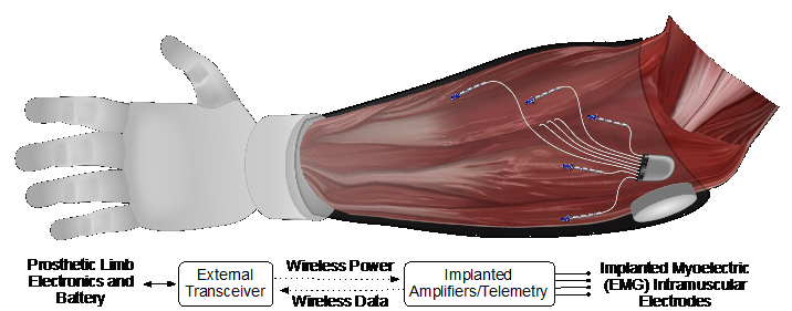
Figure 2
A 32-channel EMG recording from the implanted device during 12 seconds of walking. Channels 1-8 were located in the long head of the triceps; channels 9-20 were located in the lateral head of the triceps; and channels 21-32 were in the deltoid.
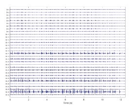
Figure 3
One gait cycle measured from the long head of the triceps showing a period of low noise during shoulder extension and an active contraction during shoulder flexion.
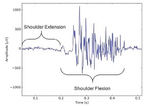
Figure 4
The range of SNR values across the 32 channels for each device. (A) The average SNR for the entire muscle activation event, including the low amplitude onset and relaxation periods. (B) SNR calculated at the peak of the muscle contraction.